Week 4
Updates from the week of April 20th
Objective
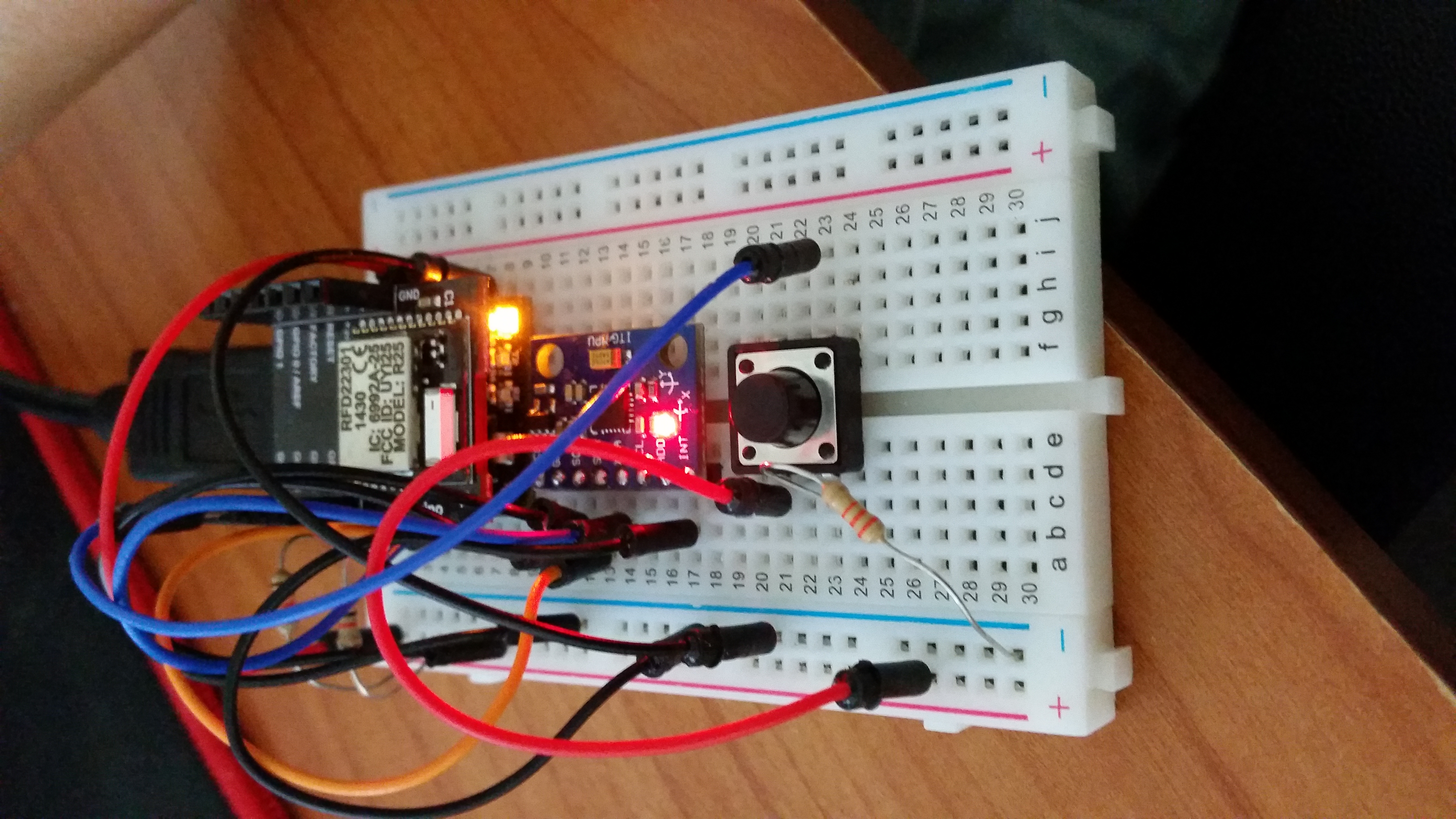
Making a simple RFduino Program & Retrieving data from IMU sensor

After we got the necessary hardware for the project, we met up with Professor Reynolds to learn about I2C.
Then Professor Reynolds went over how to retrieve data from the sensor.
From the IMU sensor, We could retrieve acceleration (x,y,z), temperature, and gyro (x,y,z).
To test the simple behaviour of the sensor, we decided to examine only the acceleration data.
To trigger the data taking, we used the button press and make it start taking data after 2 delays.
Here is the example of the code,
With this code, we were able to obtain csv of acceleration data as shown below.
Analyzing data with Matlab
After taking the data points, we started to analyze with using Matlab.
we first took the data of idle position with expecting consistent data throughout sampling.
we then made a simple motion by moving consistently and compared the data with what we had before as in idle.
Below are the x and z graphs when in idle (measuring gravity)
Determine the energy usage
We estimated our energy usage by checking the datasheeet on each of our component used.
The datasheet states for both sleep current and active current for each component.
Then I have recorded those data in the table as shown below.
With the data I have recorded, we got the pie chart as follows,
As you see, RFduino drains the most current in our device.
The total averge current is 1.55mA and the battery life expected is around 25 hours.
Discuss potential areas for problems
First, we have found that our data examination has some potential issues. Because our main goal is to make a projectile of the swing, we have to figure out the way to get x,y,z coordinates with using our accelerometer data and the gyro scope data. Since they all heavily depend on gravity and the orientation of the sensor, we will have to find the way to not depend on gravity. For energy part, because our option is limited due to the size of our device, we have to choose the right battery pack to use. For the energy usage analysis, we recorded based on the disposable AAA battery. But realistically we would want to use USB powered battery, and that will give some challenges in hardware implementation.
